ReelFeelingsFishing
Member
Hey, forum! I'm in the process of designing for and planning to convert a 7'x16' enclosed, cargo trailer into a living space I can tow. I'm a bit stumped by an element of the electrical system's design, and I'm hoping someone on the forum can shed some light or share their experience. I hope I chose the correct sub-thread to post this in! 
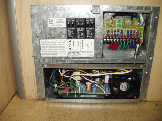
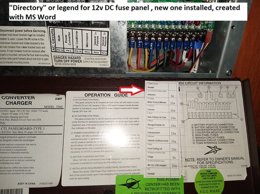
I'm planning to use a 120VAC/12VDC distribution center that I'll supply with a 30A service, and a combination of 15, 20 and 30A Square D, Homeline breakers. This is a link to the distribution center on Amazon. The bus bar for the breakers has room to accommodate 8, single-pole breakers in total, and I want to have plenty of outlets available in the trailer so I plan to use them all. My issue, though, is that the bus bar is actually two bus bars with 4 rails each, and my understanding is that you're expected to connect them with a 50A breaker. Without that 50A breaker, my understanding is that you're limited to only using one of the bus bars, half of the available breaker rails. I am going to use a 30A breaker because the F150 Powerboost's on-board generator is 30A, and the campgrounds I've visited all had 30A hook-ups.
I want to bridge those two bus bars so I can take advantage of all 8, available breaker rails, and I'm exploring different options. These are the design ideas I'm hoping folks can shed some light on. For the sake of simplicity, I am going to refer to the 8 rails along the two bus bars as 1A, 1B, 1C, 1D, 2A, 2B, 2C and 2D (from left to right).
Option 1: install one, 30A, double-pole breaker (link) across 1D and 2A. This double-pole breaker would connect both buses so I can use all 8 breaker rails. But, I understand this solution could result in a situation where 20 amps are being pulled from the left leg (rails 1A through 1C), and another 20 amps are being pulled from the right leg (rails 2A through 2C). In this situation, I understand the 30A breaker would not trip because each pole is afforded 30 amps and they're only pulling 20. My total current draw would be 40 amps on a 30 amp service, the breaker wouldn't trip, and this can result in melting wires and fires.
Option 2: install two 30A, single-pole, breaker (link) at 1D and 2A, and use a 10AWG jumper wire to connect them together. I'm thinking this will effectively bridge the two bus bar halves and will retain the intended functionality of the 30A breakers: if more than 30A is being pulled through either breaker, they should trip. The issue with this solution is that it adds the complication of having two "main" breakers that can be in different on/off (opened/closed) states, and I'd have to be very diligent about ensuring my system is properly de-energized when I work on it.
Looking forward to your thoughts and ideas! Thank you in advance for reading this novel-of-a-post and getting this far!