Multi Switch Water Pump

The friendliest place on the web for anyone with an RV or an interest in RVing!
If you have answers, please help by responding to the unanswered posts.

Huff61

New member
Joined
Mar 8, 2022
Posts
2
Location
Palm Desert
I have a 2014 fleetwood southwind 32v. My multi switch water pump stopped working, last week. I recently replaced the pump but still not working. I was reading about it could be a fuse issue, but I can’t find a fuse labeled water pump. I have a fuse box in my bedroom with 10-12 fuses in it, but nothing is labeled as to what those fuse are for. So if anybody has idea what those fuses are for I would appreciate it.
 

Attachments

  • IMG_1081.jpeg
    IMG_1081.jpeg
    203 KB · Views: 6
There is a latching relay that to which all the wall switches are connected. If none of the pump switches work it's likely a fuse, if one does work, then the latching relay is the suspect.
It's easy to test a wall switch, just remove from wall, disconnect wiring, then use a continuity meter to test each side of the switch.
Oh, edit: snap a picture of wiring before disconnecting any connections to avoid confusion later.
 
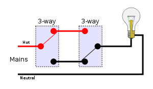
It may not be a fuse so you would be wise to get out your multimeter and trace the circuit to see if there is power anywhere. If neither of the switches work than it is probably not a switch. Some systems do have a latching relay while others with only 2 switches do not but connect them as in this picture.
1707927497307.png
 
If you have only two water pump switches the wiring will probably be what Kirk showed. If 3 or more, there will surely be a pump controller. Fleetwood used the Intellitec brand controller. And if there is a controller, the on/off switching is done on the ground side of the pump wiring, so the hot wire will have +12v at all times. And there may be an inline fuse on that hot wire.

Your first diagnostic steps should be to determine if there is +12v to the pump and if there is a working 12v negative ground. Use a voltmeter to test for +12v and then a jumper wire to connect the pump ground to a known good chassis ground point. If you have +12v and the pump runs when jumpered to a ground, then you can be sure it's a grounding problem rather than wall switches. The ground problem is either the wire or the controller module. If no +12v, then it's a power source problem. How you proceed from there depends on whether you have 1, 2 or 3+ pump switches, so I won't try to explain all the possibilities here. Let us know which switch configuration you have.
 
Last edited:
One of the handier tools in my box is an automotive test light.. Pair it with a long reel (say 20-30-40 feet( of say 18 or 20 ga Wire and a pair of allegator hooks for when needed.
Hook the clip on the light to any known good ground (or to the long wire and the other end of it to a known good ground or the battery negative) Now on blade fuses there is a tiny window on top on each end Touch tip of test light first to known good POSITIVE (Say the battery) I've found I often need to reposition the light to make it work..

Now touch the tip to each window.> BRIGHT BRIGHT Good fuse Dark Dark. No test Bright Dark or Dark Bright Replace fuse. NOT absolute (Someties it's a bad connection between fuse and fuse soccket) But usually helps to find popped fuses.

 
It doesn't appear that Huff61 has been back, or at least he has not signed on to the forum. He may be watching but just don't let us know if he found the problem?
 

Latest posts

Forum statistics

Threads
132,194
Posts
1,391,838
Members
137,902
Latest member
brianw1234
Back
Top Bottom