Transfer Switch

The friendliest place on the web for anyone with an RV or an interest in RVing!
If you have answers, please help by responding to the unanswered posts.

dktool

Well-known member
Joined
Apr 3, 2015
Posts
273
Does anyone know of a source for a stand alone 3 way transfer switch ?
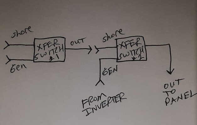
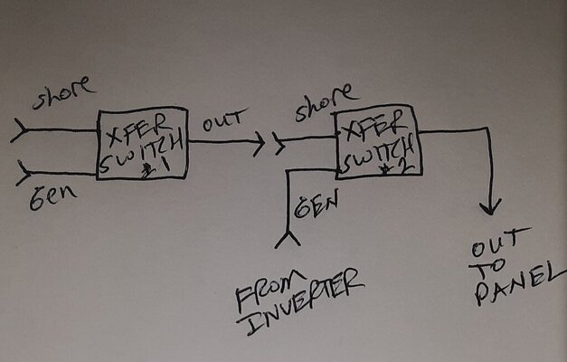
I currently have a 2 way (shore / generator) I am adding a 2000 watt inverter, if no 3 way is available I'll add a second 2 way down stream of the first.
I want the inverter to be a seamless extra power source when needed with it powering all outlets as currently wired.
I will add a N.C. relay that will disconnect the battery charger when the inverter is on.
 
A couple of things . . .

First, it sounds like you bought an Inverter/Charger, right? If so, you don't need the battery charger anymore.

Second, you don't need a new transfer switch. I'm going to assume that the output from your transfer switch goes into a 30A breaker box. I'm also assuming your 2003 Flair is 30A, not 50A. If so, then you just disconnect the transfer switch output from the breaker box and connect it directly to your new inverter. Finally, the inverter output then connects to your breaker box.

However, this wouldn't be my choice. I'd add a subpanel with all breakers except your AC . . . similar to this (ignore the solar panel stuff): 2000W Inverter/Charger system
 
The inverter is not an inverter/ charger, the existing 2 bank smart charger stays.
My unit is a 1993 and yes, 30 amp.
 
DKTool,
If you were to buy an Inverter/Charger, that would get you by that part. Then the down stream receptacles would all be live with and AC available.
Matt_C
 
I have a Renology 2K pure sign wave inverter.
This is where I'm headed unless there is a 3 way xfer switch available.

20240117_150804.jpg
 
Does anyone know of a source for a stand alone 3 way transfer switch ?
Are you looking for an automatic or manual transfer switch? If manual, you could put a 30-amp cord cap on your inverter and plug it into your camper shore power. Simple, cheap and no chance of dual feed. If automatic, what logic will you use to control three feeds?
Sounds like a fun science project.
 
I just reread your post. You are looking for seamless power transition. Your drawing is open transition. You want closed transition switching. How are you going to match phase from shore/gen to inverter and release Shore/gen? Is the inverter being used as a UPS or third power source? This is getting more sporting.
 
Some generators have a built in transfer and I recommend them (one of them is behind me as I type) Wire like this
Mains To Transfer switch
Generator To transfer switch

Transfer switch to main breaker panel
30 amp branch to 2000 watt inverter to sub (2nd) Breaker panel to Selected loads and outlets.
NOTE: As I recall Progressive Dynamics used to make a 3-Buss 50 amp breaker panel

L-1
L-2
Inverter
Both the MAIN and SUB panels in one box. But I do not know if they still make it.
 
Depending on how many outlet circuits you have, an inline relay would be the easiest option. Most likely you only have 2 or 3 outlet circuit breakers and the unit the you have is has 3 receptacles. Get one of these for each circuit. I did this and it works seamlessly. I power all outlets in my unit except the bathroom.

Install: In the power center, disconnect the wire from the back of the 15 amp circuit breaker and connect end of the relay to the circuit breaker. 2. Connect the other wire of the relay to original wire from the circuit breaker. 3. Plug in relay to inverter.

This means when you have any source of power coming from shore power or generator the relay is by passed. When there is no power coming to the power panel from anywhere the relay sees there is no power and switches over to the inverter.

I have a separate breaker for my inverter and don't need to worry about it because when there is no power to the panel that breaker has no power, only the 2 circuits I have relays on are powered. I power my residential fridge this way when going down the road. More or less, floating the batteries. The fridge uses the inverter for power and the alternator is charging the batteries as I go.

 
I just reread your post. You are looking for seamless power transition. Your drawing is open transition. You want closed transition switching. How are you going to match phase from shore/gen to inverter and release Shore/gen? Is the inverter being used as a UPS or third power source? This is getting more sporting.
The model transfer switch currently installed and if I add the second one it will be the same model have 2 N.C. and 2 N.O. contacts, the shore input uses the N.C. (Line and Neutral) to output (panel), when power is applied to the generator input the relay energizes to disconnect shore and connect generator. The relay is 100v D.C. to avoid any low voltage chatter.
The control board in the xfer switch does the rectifying and also has a selectable time delay 0 or 20 seconds on the generator input to allow the generator to stabilize and run it's self check logic if applicable.

So both shore to output in this drawing are N.C.
20240117_150804.jpg
So transfer #2 doesn't care what is going on upstream when the inverter comes on, upstream has just been de-coupled.
 
Last edited:
Do you plan to operate the entire RV from the Renology inverter? Keep in mind that the most it can supply is about 16A to your 30A RV. When supplying the 16A of loads it will need slightly more than 160A from your 12V batteries.
It will be used for coffee maker and or toaster and or microwave. 2 at a time max with that wattage.
2000 watt load is more like 200 amps after loss. (no free lunch)

D.C. side will be #1 cables with a round trip distance of less than 5 feet.
4, 6 volt batteries.
250 amp breaker
 
You require phase syncronized sources and that cannot be achived with relay transfer switches.
A solution I have engineered in the past used a Victron Multiplus inverter charger with a relay transfer switch.
basically: the transfer switch is wired to shore and generator, the output of the transfer switch is fed to the victron unit, the victron unit then provides 120V output either from the transfer switch source or from batteries, all phase syncronized. The system then acts as an uninterruped power supply.
the victron unit also has an output to start the generator if batteries are low as well.
 
Why would it require phase sync when it is not intended to be ups ?
The oem shore to gen does not, this is merely a 3rd power source which copies the oem switching logic.
 
Why would it require phase sync when it is not intended to be ups ?
The oem shore to gen does not, this is merely a 3rd power source which copies the oem switching logic.

from your statement : "I want the inverter to be a seamless extra power source when needed with it powering all outlets as currently wired."

this implies and requires phase syncronous sources from the first transfer switch to the second, if however you meant to state "I need an automatic way of switching power sources" then a relay setup would work.

with relay switches, there will be a delay transferring power from each source, a typical delay might be from 5 to 15 seconds so it's not a UPS, but an unattended transfer with a period of power loss.

if that satisfies your requirement then dual 2 way or single 3 way xfer switches will do the job.
 
You require phase syncronized sources and that cannot be achived with relay transfer switches.
A solution I have engineered in the past used a Victron Multiplus inverter charger with a relay transfer switch.
basically: the transfer switch is wired to shore and generator, the output of the transfer switch is fed to the victron unit, the victron unit then provides 120V output either from the transfer switch source or from batteries, all phase syncronized. The system then acts as an uninterruped power supply.
the victron unit also has an output to start the generator if batteries are low as well.
This is the type of function I was going to suggest, AC current routed thru the inverter. It can also use the batteries to boost the existing shore power passing thru it for starting air conditioners, etc.

I'm generally not fond of all in one devices but in this case, this fixes everything.

Charles
The victron units really are high quality and work well. There are different solutions, but that particular unit is a good one.. It's an inverter/charger with xfer switch. it will act as a UPS as well as a charger. i favor and use that unit in my own TT along with their MPPT controllers. for the funtionality, they are a cost effective solution.
 
Back
Top Bottom