chaostactics
Well-known member

You need to show a little more detail.
It looks like your battery bank is not shown and is located below the schematic where the shunt on the negative black line and the disconnect is shown by the red heavy line is.
You will want a catastropic fuse either before or after the disconnect by the invertor and a inline fuse that maybe shown next to the solar disconnect and maybe another at the output from your charge controller.
We need detail on the size of your battery bank and the rating of your invertor to calculate you draw from the batteries in amps. It should be specified in your invertor documentation.
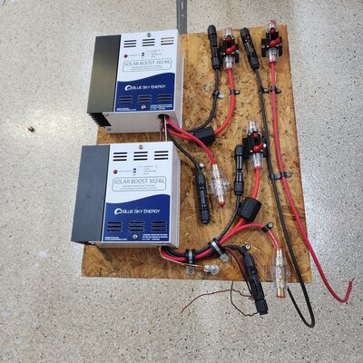
The size of your controller inline fuses before and after the controller are based on the amps thru the combined feed from the panels in series,


I'm seeing anywhere between 32-75 amps in my searches for allowable amperage for 6 gauge.I don't know what to make of that diagram, but Mark has given the definitive answer. The fuse rating should never exceed the wire amp capacity, which is primarily limited by the wire diameter (gauge). You can go with a lower amp rating if you are confident the combined amp loads on the circuit are smaller, but that is at your option. In simplistic terms, the fuse protects the wire, not the devices on the circuit.
I'm seeing anywhere between 32-75 amps in my searches for allowable amperage for 6 gauge. The median number seems to be 55 amps. My wire length is going to be less than 2 feet, hopefully less than a foot.Generally you fuse for the wire gauge. You can go less from there if you want. After that the fuse has to be rated for the voltage.
Mark B.
Albuquerque, NM

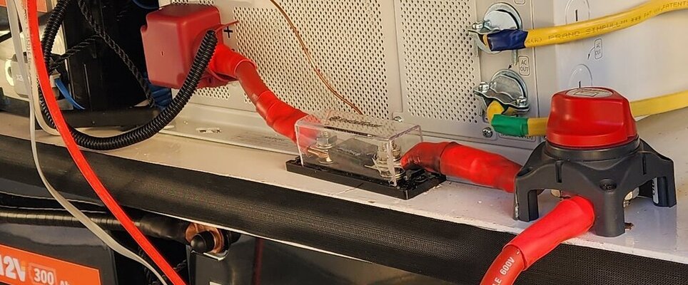
The battery has a 300 amp ANL fuse inline with the positive line. the batteries are 2/0 as is the line from the Lynx to the inverterI would recommend a 60 amp inline fuse from the controller to the bus bar.
You could use a 50 amp but you might end up changing it often.
Back to the battery to invertor issue. You might be surprised at how much the invertor under load can draw. A cat fuse at the output from the battery to the invertor is a good idea. Check your invertor documentation for the value. I am sure that the wire size from the battery is much larger than 6 guage.
Your buss bar might have a fuse but I do not see it or maybe it is located by the battery bank and not shown in the schematic.
I used 1/0 battery cables on my system.
For a supply from a Lithium battery, an ANL fuse is not suitable. It has to do with interrupt ratings. The best explanation is to read this thread on the Escape trailer Forum, started by TDF-Texas.The battery has a 300 amp ANL fuse inline with the positive line. the batteries are 2/0 as is the line from the Lynx to the inverter