Isolator

The friendliest place on the web for anyone with an RV or an interest in RVing!
If you have answers, please help by responding to the unanswered posts.

WME

Well-known member
Joined
May 4, 2023
Posts
144
Location
Riverton WY
2003 Brave 30ft Workhorse
Short version..I replaced my 2 old golf cart batteries with 2 LifePo4 100ah batteries.
To protect the alternator I am charging the lipos with a 40 amp DC to DC charger, all is good. BUT I need to disconnect/unplug the isolator so I don't have parallel charging.
I have the Winnebago coach wiring diagram and the Workhorse chassis wiring diagram. Neither are overly useful as there is no interconnect between them.
I've tried various combos of removing wires and unplugging control wires. I get no change or more common something stops working, steps, converter charging, or everything stops.

Does anybody have a simple way to make the isolator stay open? and everything else still work???
 
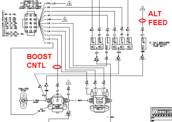
Seems if you don't care about being able to bridge the chassis and house with the boost switch you can just disconnect that solenoid (coil wire). Then it would act as though the key is off all the time, still retaining whatever equipment runs on just chassis (genset, steps) and just house (house stuff). If you wanted to retain the boost function you might need to dig into it a bit more but is likely doable with what's there.

Edit, looking at the diagram for mine it might be as simple as lifting a wire from the chassis in the breaker box. Not sure how similar yours is to mine though (2005).

1684271323964.png

Mark B.
Albuquerque, NM
 
Last edited:
On the isolators I’ve been around, the yellow wire went to an ignition ON source. What ever color your ignition on wire is, I believe that when it is not energized, the house battery will not charge, but the chassis battery will.
 
I think I've been to the yellow wire and it didn't work right. BUT I was doing a lot at that time and there is a "possibility" that I measured wrong, so I will revisit it and write down voltage measurements.
 
Your boost switch has 8 terminals but only 3 are used, #1 is wire LS and is 12 gauge yellow, #2 terminal is wire LR and is 14 gauge yellow, and #3 terminal is OOC and is 14 gauge yellow.

WBO marks all of their wires so it should not be too difficult to identify the wires, and the switch should have terminals numbered on the rear.

Ref "Automotive wiring diagram" sheet 1, figure 2, is marked in the very lower RH corner as page 3, it is the second drawing, and the boost switch is in grid column 14 at the very top.

To orient yourself, The second drawing is the center drawing. the first drawing sits to and connects to the right side of the second drawing, and the third drawing sits and connects to the left side of the second drawing.

If you follow the wire LR on terminal #2 it passes thru the harness and two connectors, and ends up on the small terminal (coil) of the boost relay. ref Body 12 volt wiring diagram on sheet #4 marked as page 07 in the lower RH corner of the sheet. the boost relay is in grid B7 and is called a "battery mode solenoid"

DO NOT disconnect wire LR any where! if you want the boost function to continue to work.

*************

The wire on boost switch terminal #3 is KE and is supplied by a fuse found in Automotive wiring diagram we looked at above and is found in sheet 3, page 08 in the fine print, lower RH corner. Look at grid D2/3 fuse 5 labeled "Gray". KE is basically a ignition power wire that supplies several things including the boost switch

The wire on boost switch terminal #1 is, as we said, wire LS and is 12 gauge (larger than the other two), and runs down to a splice and then to both the left and right so it connects to both the drawing above it and the one below it. It goes to a lighter socket, a 12v power socket and a couple of other things.

I would start with unplugging wire KE from the boost switch and see what works and what does not, as I suspect that will kill the power going to the boost relay when the ignition is turned on. If it does, try the boost switch and see if the relay still clicks (engine off, ignition off) when you push the boost switch.

When you finally settle on something, put heat shrink over the terminal end of the wire you disconnect, and tag it as to where it was removed from. Someone in the future may want to reconnect it.

Charles
 
On the isolators I’ve been around, the yellow wire went to an ignition ON source. What ever color your ignition on wire is, I believe that when it is not energized, the house battery will not charge, but the chassis battery will.
Removing wire LR as Mark noted above (virtually the same as the OP's drawing) will kill both boost AND charge modes. If the OP in not interested in boost start capability, removing the wire LR from the solenoid is the easiest way to go.

Charles
 
I think I got it. It sure is a lot easier when somebody knows their way around a Winne and I don't have to flip page after page to chase a wire
Thanks again to all.
P.S. Didn't mess with any yellow wires
 
Wondering, are the wire markings consistent with functions across RV models? I haven't correlated them myself to any model but mine, but man, it's money from home when you're trying to ring something out.

Mark B.
Albuquerque, NM
 
Wondering, are the wire markings consistent with functions across RV models? I haven't correlated them myself to any model but mine, but man, it's money from home when you're trying to ring something out.

Mark B.
Albuquerque, NM
Kinda sorta similar, the relay and solenoid are there. I have the 7 CBs but they have different values and the power parallel feeds are different. But the black wire you labeled ALT feed is there and going to the solenoid. I disconnected it from the 40 amp CB and removed the shunt between the next 2 CB and installed it there. So undo is simple move wire back to original CB and redo the parallel shunt.

The year, Ford or Workhorse and length may all effect the actual wiring
 
Winnebago low voltage house wiring color code is yellow for positive and white for negative. Having individually numbered wiring is a huge advantage for troubleshooting. Sometime after our 2005 Horizon, Winnie was supposed to start numbering 120V wiring. Not sure if they ever followed through with that.
 
Back
Top Bottom